
Five recent schemes
Client names are withheld. The numbers are ours, taken from the issued design reports.
Pool hall AHU replacement, four leisure centres
The problem
A London borough needed the pool hall air handling units replaced across four leisure centres, in parallel with a heat pump scheme and a borough-wide BMS upgrade. There was no reliable record data for the existing units, and the humidity set points the selections would rest on had never been properly derived.
Getting that wrong in a pool hall means condensation on the coldest surface in the building, which is expensive to put right and hard to hide.
What we did
Rather than assume a generic 60% RH, we derived the limiting room dew point from the lowest internal surface temperature in the thermal model, checked hour by hour across a full London weather year, with a 2 K safety margin. Pool evaporation was calculated by the Biasin and Krumme method at the design activity factor.
The selection turned out to be governed by the winter heating airflow rather than by moisture control, so the unit duty is not sensitive to the humidity assumption. That removed the largest open risk from the programme. This is ventilation and air handling design rather than a plant swap.
The outcome
A like-for-like rooftop replacement in the existing position, avoiding new roof penetrations, with duties fixed as the minimum performance basis for tender so every manufacturer quoted the same thing.
The review also picked up two errors. The AHU schedule specified 55/45 °C LTHW while the RFI register said 50/45 °C, and fan heat gain had been left at zero, worth about 1 K of supply air temperature on a unit this size. Both were resolved before issue.
Grid connection and metering for two school heat pump schemes
The problem
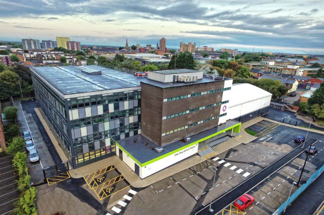
A trust in the north east had funding to take two schools off fossil fuel, one on gas and one on oil, both with boilers at end of life. Our scope was the Stage 3 mechanical and electrical design, the grid connection and the electrical metering.
On a scheme like this the risk sits with the electricity supply rather than the heat pumps. A connection quote that arrives after the funding is fixed can end a project. Electrical capacity and DNO engagement are part of every heat pump design we do.
What we did
We metered rather than estimated. Four weeks of incoming demand monitoring at both schools, for £2,200, instead of sizing the connection from a fuse label. One school's actual maximum demand came out at 28 kVA, so the new connection was being driven entirely by the heat pumps rather than by the school.
The DNO enquiry went in before the funding application rather than after it. The quotation came back with two routes: the network operator carrying out the contestable works at £81,464, or an independent connections provider doing them at £10,213. That choice was only available because the enquiry was raised early enough to act on.
At the second school the installed boiler capacity was 130 kW against a calculated peak load of 34 kW. Sizing the heat pumps from the old boiler nameplate would have almost quadrupled the plant, the connection and the cost.
The outcome
A 190 kVA connection offer accepted on evidence, plant sized from calculated load, and a diversified electrical design that stood up to scrutiny.
We then reviewed the contractor's Stage 4 drawings and raised seventeen comments. Among them, panel heaters had been added to spaces that were not previously heated, which would have increased the maximum demand and the substation size after the connection had been agreed. We also asked for the heat pump metering to be cabled back to the BMS so the system can be checked against design intent once it runs.
Heating feasibility for a listed school with no gas supply
The problem
A rural secondary school of nearly 7,000 m², parts of it Grade II listed, heated by oil and bulk LPG across five separate plantrooms with no gas network available. The oldest boilers pre-date 1990 and spares are becoming hard to get. An earlier biomass installation had been tried and had not worked.
What we did
We built the baseline from fuel stock reconciliation and supplier records: 426.8 MWh of fuel in, 356.6 MWh of useful heat, £27,172 and 102.6 tCO2e a year. The report states that this is accurate to within about 15 to 20% and lists what would tighten it. One anomalous oil price in the source record was kept and flagged rather than smoothed out.
Installed boiler capacity across the site is roughly twice the benchmark peak load, so we sized from a load duration argument rather than matching nameplates. 250 to 300 kW of heat pump, around half the peak, covers 80 to 88% of the annual heat.
Five options were costed from £0.1m to £3.5m. A river source scheme was rejected with the numbers set out: 380 kW drawn from the river implies roughly 30 l/s of flow and an abstraction licence, before a 500 m pipe route and the consenting that goes with it.
The outcome
A phased hybrid recommendation, with heat pumps as lead plant and LPG retained for peak load and morning warm-up. It is not the lowest carbon option on the table, at 67% against 82% for full electrification, and the report says so and explains why. Full electrification would need 240 to 280 kW of electrical demand against a supply whose spare capacity nobody has established. The 400 A incomer label is a constraint to investigate, not headroom to spend.
The report also states that at current prices electrification does not reduce the energy bill. The benefit is carbon. It is better for a client to know that before committing than after. That is how we write every feasibility study.
Plant replacement at a listed city museum
The problem
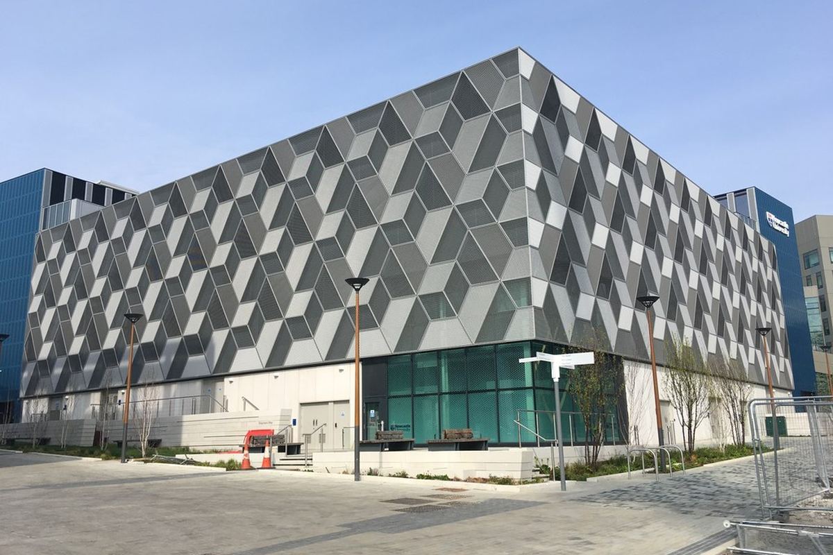
A listed museum heated by gas, with one boiler already out of service and an 18-year-old chiller at the end of its life. Because the collections need humidity control all year, the plant runs in some form for around 7,750 of the 8,760 hours in a year. The Stage 2 concept study had assumed about 400 kW of heating load, taken from equipment schedules rather than from what the building uses.
What we did
We validated the design basis against a full year of half-hourly gas metering, matched to the museum's own roof temperature sensor. The highest half hour of the year was 404 kW, close to the Stage 2 figure, but every one of the fifteen highest readings fell at 05:00 or 07:30. They were warm-up surges produced by the plant's scheduling, not demand from the building. At the coldest design condition the steady demand is around 120 kW.
The chiller sub-meter showed genuine cooling on 237 days, so this is not a summer-only load. Peak cooling, rather than peak heating, is what makes two units necessary.
The outcome
Two propane heat pumps on the roof in the chiller's position, reaching 80 °C so the existing radiators and air handling coils stay as they are, with a staged electric boiler in the basement for the coldest mornings and all gas plant removed. More on how we approach heat pump design.
“Running cost is broadly neutral. We would not present this as a money-saving project. The case for it is carbon, the condition of the existing plant, and taking gas out of a listed building.”
Open items, reported rather than left
- Cooling-mode noise sits 7 to 10 dB above the council limit, so an acoustic consultant was recommended before the roof arrangement is fixed. In heating the plant is comfortably inside it.
- A 400 kVA connection agreement, but the incoming cable appears rated at less than half that. A hard limit goes into the BMS whatever the answer.
- Two units need 6.8 m against the 6.0 m the existing enclosure gives. Removing one run of acoustic screen releases 1.5 m. Three units would need 9.2 m and will not fit.
- The manufacturer requires 600 litres of buffer volume per unit. The building has none, and Stage 2 had assumed otherwise. New scope.
- Roof loading and listed building consent both need resolving before the arrangement is fixed.
Packaged external plantroom for a site with no plant space
The problem
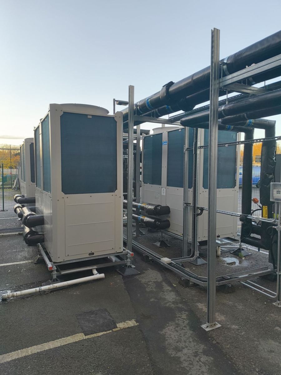
A site with no internal plant space and an existing LTHW system that had to keep running. Heat pumps, boilers, buffer vessels, pumps, pressurisation and water treatment all had to go outside, in a compound that would still be maintainable in ten years' time.
What we did
We designed the plantroom as a package with three separate LTHW circuits for the existing system, the boilers and the heat pumps. Each has its own pressurisation, expansion and side stream filtration, so the low temperature heat pump circuit is hydraulically separated from the higher temperature boiler circuit through plate heat exchangers.
Full equipment schedules were issued for boilers, pumps with flow rates uplifted 10%, pressurisation units and expansion vessels, buffer vessels, heat exchangers and side stream filters. Every duty was calculated in the schedule rather than left for the contractor to assume.
The outcome
A compound set out for access and lifting from the start, with acoustic and maintenance clearance designed in, and a schedule set complete enough that manufacturers could be compared like for like at tender. Where a scheme like this is monitored afterwards, Jupiter Performance reports what the plant delivers.
The rest of the portfolio
Rural leisure centre, Shropshire
A £2.35m scheme carried from Stage 3 through to Stage 5 construction issue, including the BMS description of operation and the DNO engagement.
Swimming pool, Lancashire
Stage 3 and 4 mechanical and electrical design, then Stage 5. Full wet-side plant and electrical distribution.
Secondary school, North Yorkshire
A £2.7m ground source heat pump scheme, from Stage 2 electrical performance specification through detailed design.
Civic leisure estate, West Yorkshire
A three-site decarbonisation plan comparing a district heat network, heat pumps and 188 kWp of solar. We recommended waiting for the network and taking the solar now.
Aerospace facility, Cheshire
Electrical load assessment and condition reporting across seven industrial buildings.
Supermarket and retail programme
Stage 3 and 4 mechanical, electrical and public health design across a rolling national new-store programme, and fit-out for several fashion and lifestyle brands.
Send us the scope
A building, a stage, a date. We will come back with whether we can take it, what it costs and what we would need from you — usually within a working day.
About these case studies
Why are the clients not named?
Most of our work is delivered under an appointment that vests publication consent in the client rather than in us. We are working through those permissions. The technical content and the figures are unchanged; only the names are withheld.
Where do the numbers come from?
The issued design reports. They are our calculations, not estimates written for a website.
Can we see a full report?
Where the client agrees, yes. Ask and we will seek permission to share a redacted study relevant to your building type.
Can we speak to a reference?
Yes. We will introduce you to a client with a comparable building and comparable constraints.